Keyboard and Mouse Controls
The Toolbar
|
|||||||||||||||||||||||||||||||||||||||||||||||||||||||||||||||||||||||||||||||||||||||||||||||||||||||||||||||||||||||||||||||||||||||||||||||||||||||||||||||||||||||||||||||||||||||||||||||||||||||||||||||||||||||||||||||||||||||||||||||||||||||||||||||||||||||||||||||||||||||||||||||||||||||||||||||||||||||||||||||||||||||||||||||||||||||||||||||||||||||||||||||||||||||||||||||||||||||||||||||||||||||||||||||||||||||||||||||||

|
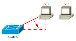
To link objects, firstly use the Link Style Dropdown Box Click the link button You may also right-click an object and choose "Link" to enter link mode. To finish linking objects, click the link button Clicking the background whilst in link mode enables you to form joins (elbows) in links (See also the link break feature). Clicking an existing link automatically sets the Link Style Dropdown Box to the matching link style. To modify or create link styles see Formatting Link Styles. |
 |
Tip: Double right click the background to toggle the last used mode (Paste, Text, or Link) off and on.

Link Align
|
|
 |
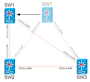
Moving A Link From One Object To Another
|
|
 |
Layers (Drawing Order)
|
|
|
Background Objects
Setting an object to be a background object in the Object Properties form enables you to draw multi-segment links over the top of an object without connecting to it.
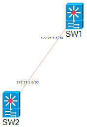
Unlinking Objects
To remove links between objects, right-click the link
and choose delete or select the objects which are linked and then click
the Unlink Button ![]() .
.
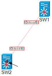
Using the Link Break Feature
The Link Break Feature enables you to break a link and
create a join anywhere on an existing link. When you right-click the
link and select Break a new "link-node" is highlighted which you
can then drag and drop or nudge to the desired position.
To remove a
join select the link-node which forms the join and delete it.
Moving and Copying Objects
To move selected objects, hold the left mouse
button down on an object for 1.5s and then drag and drop. Alternatively
holding the Shift Key down enables drag and drop immediately.
To copy objects, select them and then click the Copy Button
![]() .
Click the Paste Button
.
Click the Paste Button ![]() to enter Paste Mode and the position the cross hair and left click to
paste copies of the objects. To finish pasting, click the Paste Button
to enter Paste Mode and the position the cross hair and left click to
paste copies of the objects. To finish pasting, click the Paste Button
![]() again, or double right click the background to exit the current mode, or
hit the escape key.
again, or double right click the background to exit the current mode, or
hit the escape key.
Nudging Objects
To nudge selected objects, hold down the Shift key while pressing one of the cursor keys.
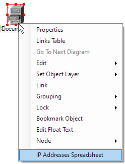
Setting An Object's IP Address
To set an Object's IP Address, right-click the
Object and choose "Properties".
Enter the IP address in the Address
field. For more information see Object Properties.
Changing The Name (Or IP Address) Of An Object
To change the name of an object or change its
IP address, Double Left Click on current name or IP address and type in
the new details. Press Enter to complete.
You may also change these details by right clicking the object and selecting
"Properties".
To insert a Carriage Return in an Object or IP Label
use
Shift + Enter.
Adding Text To A Diagram
|
Click the Text Mode Button Tip: Double right click the background to toggle the last used mode (Paste, Text, or Link) off and on. |
|

Editing Text
Double click text to start editing it. The Text Mode
button will indicate you are in text mode. Press ESC to finish editing the text, or click the text mode
button on the toolbar.
To delete a Text Box, double click it and then hit backspace. Press
ESC or click the text mode button to exit text mode.
Formatting Text
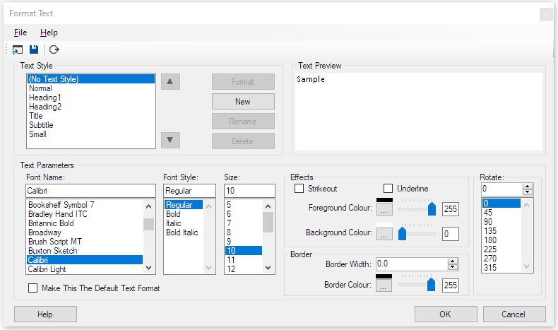
To Format Text, right click text in your
diagram and select Format Text. The Format Text window is now
displayed. From here you can set the Font, Font Size, Colours,
Transparency, Effects and also set the angle of rotation in degrees.
You can also select Format > Text Styles from the main ring menu to
make adjustments to Text Styles.
| Text Style: | Commonly used text formats can be created and named using these settings. Right click text in your diagram and choose Set Text Style to select from defined text styles. Text Styles can be saved to and loaded from file. |
| Make This The Default Text Format: | Sets the default text format used when adding text to a new diagram. |
Moving Text
To move text, hold the left mouse button down on
the text for 1.5s, then drag the text to the new position.
Alternatively hold the SHIFT key
down and drag the
text.
To Rotate Text, hold the SHIFT key down and drag one of the
corners of the text.
Text Types
Text can be set to one of four possible types by right-clicking and choosing "Set Type":
| "Default" | - For standalone text. Enter key adds a new line. Use escape key (or button on toolbar) to submit. |
| "Caption" | - For normal object captions. The enter key or escape key submits (or button on toolbar). Shift-Enter adds a new line. |
| "Address" | - As caption label, but is displayed according to the Show/Hide IP Addresses button on the toolbar. |
| "Flow" | - Caption for flowchart symbols. Enter key adds a new line. Use escape key (or button on toolbar) to submit. |
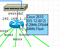
Adding Float Text To Objects
Information can be displayed when the pointer is held over an
object for a few seconds.
To Add or Edit Float Text, right click the object and select Edit Float
Text.
Enter text into the Float Text entry box and hit escape when complete.
Float Text can also be accessed from the Float text tab in the Object
Properties
form.
Text Properties Toolbar
![]()
The Text Properties Toolbar is optionally displayed
by selecting Options > Text Properties Toolbar. It provides access
to the properties for the most recently clicked text or if no text is selected
it provides access to properties for the current font which is used when
adding new text.
The controls displayed on the toolbar
are covered in the Format Text section above.
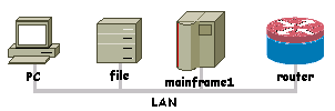
Adding Backbones
|
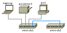
Add horizontal and vertical backbones to your diagram by selecting them from
the Backbones object library. |
|
Resizing And Moving Backbones
To resize a backbone, position the mouse pointer over either
end then hold the left mouse button down to drag the backbone larger or
smaller.
To move a backbone, hold the shift key down whilst dragging the backbone to
a new position.
Customizing Backbone StylesBackbones are Shapes and they can be customised by right clicking and select Format Shape. |
|
Linking An Object To A Backbone
To link an object to a backbone, click on the link
mode button ![]() and then join the backbone to the object.
and then join the backbone to the object.
Grouping and Locking
Objects may be grouped together and then locked in position relative to each other to form composite objects.
The first object you select will become the "parent" object and further
objects selected will be "child" objects.
Select the parent object, followed by the child objects and then select
Format > Group from the ring menu to group the objects together. At this
point, you may still move the objects relative to each other. Copying and
pasting the parent object will copy and paste all of the child objects as
well.
To lock the child objects position relative to the parent object, right
click the child object and select "Lock" from the menu. Now when you move
the child object, the parent and all of its child objects are moved
together. If you resize the parent object all locked child objects are
also proportionally resized and moved.
Right-clicking a parent object and selecting Lock > Group Lock or Group
Unlock locks or unlocks all child objects and labels associated with the
object.
To ungroup objects, select each of the members of the group and
then click Format > Ungroup on the ring menu.
Example using the two shapes created in the Custom Shapes section to form a composite Title Box object:
|
|
Position the two shapes to form a title box. |

Locking objects which are not a member of a group is used to lock the position of the object on the page. This is useful for things like template borders and title blocks which don't normally need to be moved. Objects locked to the page have the following properties:
- They cannot be moved with drag and drop.
- They cannot be selected with CTRL-A or by dragging a band around them.
Anchoring and Locking
Anchoring fixes the position of objects and text relative to one of
the four corners of the page. This is useful when resizing the
page to ensure a title block and border remain fixed to the edge.
Select objects and text to be anchored and then Format > Anchor from the
menu.
Locking objects and text prevents them from being dragged to a
new position (relative to their parent) and also prevents them from
being selected and unselected using CTRL-A. It is useful if the title
block and border are locked. You can then select your diagram using
CTRL-A and reposition it using drag and drop or nudge, without adjusting
the position of the title block and border.
Select objects (link
nodes) and text to be locked and then Format > Lock or right click
objects or text and select Lock.
Rotating Objects and Text
|
Rotate objects and text using any of the following methods:
|
 |
Display or Hide IP Addresses
To Display or Hide IP addresses, toggle the IP Address
Button ![]() on the toolbar.
on the toolbar.
|
 |
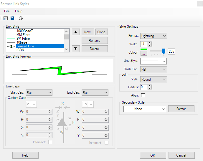
Formatting Link Styles
Select Format > Link Styles on the ring menu or right-click a link and select Format Link style.
|
|
||||||||||||||||||||||||||||||||||||||||||||
The Up and Down Arrow buttons enable you to change the order in which Link Styles are presented. Style Settings
Line Caps
File Menu Options
|
|
 |
Curve2 Link StyleCurve2 Link Style allows you to draw curved Links with any number of
control points. |
 |
Managing Link Styles
Every page in a document contains a set of link
styles. When you access a page in a document the drop down list of link styles on the
toolbar is populated with that page's set of link styles.
From the Format Link Style form you can save the current page's link styles
to a file. On the same menu, "Open" is used to load and replace the
current page's link styles.
A default set of link styles is stored in the linkdefs.nls file. This file
is used to populate the link styles when you start Network Notepad and when
starting a new document and when inserting a new page provided you select
"None/ Blank" when prompted to select a template. If you select any other template, the
page will use the link styles stored in the template file.
You can replace the default link styles by saving link styles to the
linkdefs.nls file (It may be worth making a backup copy of the file
first).
To replace a set of link styles in a template, locate the templates folder
using "File > Open Templates Folder" on the main menu. Open a template file
and then from the Format Link Styles menu load a set of links styles, save the
template file and close the document. See also templates.
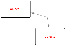
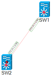
Attaching Labels To Links
|
When labels are attached to
links, by default they are rotated automatically to follow the slope of the link. |
 |
How To Attach Labels To A Link
 |
 |
 |
 |
1. Place labels in approximate positions using the text tool. |
2. Select the link first (black/red circle indication at link termination point) then select each of the labels. |
3. Click Format and then Group. The labels are grouped with the link and are automatically rotated to follow the slope of the link segment. Selecting the link now also highlights the related labels. |
4. Finalise label positions using Drag and Drop or nudge. |
Switching Off Label Rotation
Right-click the label and untick "Rotate to follow slope".
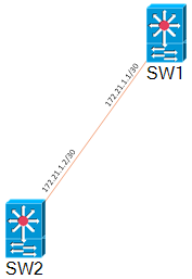
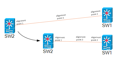
Alignment PointsThere are three alignment points on a
link segment, one at each end and one in the centre of the
link segment. The position of a label is relative to the
nearest alignment point when the label was first grouped
with the
link. Detatching A Label from A LinkTo detach a label from a link,
right-click the label and click Ungroup in the context menu. |
 |
User-Defined Apps
A list of user-defined Apps is presented for execution
when you right click an object. The first 6 of the Apps are also
available using the function buttons on the main toolbar:
![]() .
Variables such as IP address or hostname of the object can be included
in the App definition.
.
Variables such as IP address or hostname of the object can be included
in the App definition.
A set of user-defined Apps is called a
toolset. Multiple toolsets can be configured for use with
different types of equipment and then assigned to the objects in your
diagram from the Object Properties form.
Configuring User-Defined Apps |
|||||||||||||||||||||||||||||||||||||||||||||||||||||||||||||
|
|
|||||||||||||||||||||||||||||||||||||||||||||||||||||||||||||
| Command Line: | This is the command which is executed when the app is
selected. |
| Display Title: | This is the text displayed in the menu. If left blank the Command Line is displayed instead. |
| Hide: | If set to true will minimise the Network Notepad window when the app is run. |
| Multiple: | If true then the tool is run against all selected objects. If false then the tool just runs for the most recently clicked object. |

Variables
The following Network Notepad variables may be included in the Command Line and Display Title definitions:
| $IPADDRESS | Substituted for the most recently clicked
object's IP address. $IPADDRESS is truncated at a "/" character. |
|
| $ADDRESS | Substituted for the most recently clicked
object's IP address (and is not truncated like $IPADDRESS). |
|
| $HOSTNAME | Substituted with the most recently clicked
object's hostname. |
|
| $BROWSE | Invokes the default browser/application. E.g.1. $browse http://$ipaddress..... will open the object's ip address in a web browser window. E.g.2. $browse c:\docs\$hostname.doc..... will try and open for example "router1.doc" in whatever application is configured to handle .doc files. |
|
| $EXPLORE | Invokes an instance of Internet Explorer. E.g. $explore $ipaddress...... to browse the object by ipaddress. |
|
| CopyToClipboard | Copies the resolved definition to the windows
clipboard. |
|
| $FILENAME | Substituted for the current diagram's filename
(.ndg). |
|
| $VAR1,$VAR2 | User variables. These are set in the Object
Properties Form on the Misc Tab and can contain any user-defined
data. Ellipsis buttons are provided to browse for filenames. E.g. $browse $VAR1..... Could be used to open a specific file associated with the object. |
|
| $FieldN | Passes field number N from the object table.
e.g. the CDP user-defined app tool definition includes $field2
to pass the object number which it then uses to construct the
data put on to the clipboard. |
|
| $HWND | Passes the Network Notepad Windows Handle. |
|
| $ADDRLIST | Functionally the same as $ADDRESS, but intended
to pass a list of IP addresses separated by ";" characters. |
|
| $APPDIR | Substituted with the Network Notepad
installation folder. For the Professional Edition it usually returns C:/Program Files(x86)/Network Notepad Professional/ For the Enterprise Edition it usually returns C:/Program Files(x86)/Network Notepad Enterprise/ For Network Notepad Client it usually returns C:/Program Files(x86)/Network Notepad Client/ |
|
| $DOCVAR1 | Per-document user variable which is
configurable in the Diagram Properties form. |
|
| && | Enables multiple apps to be called in one
definition. See the Wake-On-Lan Tool example below. |
Example Command Lines:
- Use SSH to connect to a device using Putty:
"C:\Program Files\putty\putty.exe" -ssh $IPADDRESS
In this example putty.exe has been installed to the Network Notepad program folder:
putty -ssh $IPADDRESS
- Use Putty in telnet mode to connect to a device:
"C:\Program Files\putty\putty.exe" -telnet $IPADDRESS
- Open a web browser session to a device's IP address:
$BROWSE http://$IPADDRESS
- Remote control a device using VNC:
"C:\Program Files\UltraVNC\vncviewer.exe" $IPADDRESS
- Remote Desktop:
C:\windows\system32\mstsc.exe /v:$IPADDRESS
- Open a spreadsheet to access for example asset information for
each device in your diagram:
$BROWSE "F:\Asset Files\$hostname.xlsx"
- NNPing Tool:
NNPing $IPADDRESS 1000 3 up.wav 3 down.wav - Wake-On-Lan Tool:
NNPing $IPADDRESS 1000 3 up.wav 3 down.wav on&&nnwol.exe $VAR1
Where && is used to separate and execute multiple apps.
User variable $VAR1 is configured in the Object Properties form on the Misc Tab and is set to provide
<broadcast IP address> <port> <mac-address>
e.g. 192.168.1.255 9 21-3a-55-37-6e-76
The nnping "on" parameter overrides the usual toggle-on, toggle-off state when calling nnping.
|
 |
Tip: Enclose file pathnames containing spaces with quotation marks as shown in the first three examples above. If you don't do this then Windows cannot distinguish the difference between c:\program files and c:\program.exe for example.
| Copy Tools From Other Toolsets: |
When creating a new toolset you can use this option
to list all tools in all toolset and tick those you wish to copy to the
new toolset. |
| Up/ Down Buttons | Change the order the tools are presented by moving the selected tool up or down in
the list of tools. |
| Toolset: | Network Notepad Professional and Enterprise Editions allow you to define multiple toolsets. You can choose a toolset to use
with an object in the Object Properties form. |
| Naming Toolsets: |
Toolsets can be named by entering text in the Toolset dropdown list in
place of the default numbers. |
| Add Toolset Button
|
If you need more than the default 10 toolsets,
you can add more with this button. |
| Edit Button
|
Toolset definitions are stored in a local tooldefs.txt file. This button enables you to edit the file directly, making it easy to copy, paste and share toolsets. Here is an excerpt from a tooldefs.txt file: |
|
|
|
| When editing the tooldefs.txt file keep the numbers in
brackets in order. That is (toolset number) in the case of the
Toolset statement and (toolset number, tool number) in the case of the
Command, Display,Automin and Multiple statements. When you have finished editing the tooldefs.txt file, save the file and then click the Refresh button in the Setup form to re-read the file contents into Network Notepad.. |
| Refresh Button
|
The refresh button is used to re-read the tooldefs.txt file after editing it outside of Network Notepad. The tooldefs.txt file is written to when you click the OK button. |
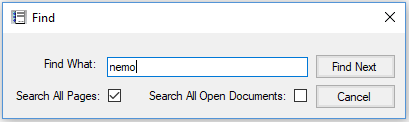
Tip: Network Notepad Files are stored as plain text. Use Windows "Search for Files" to scan through all your diagrams and find what you are looking for.
THE OBJECT PROPERTIES FORM |
Object Properties Form
|
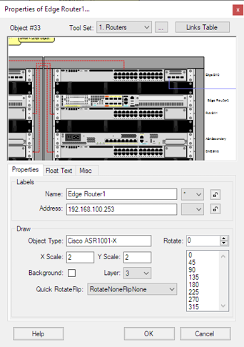 |
| Layer: |
Sets the order which the object is drawn. The backdrop and grid
lines are drawn first followed by objects, labels and links at layer 5 up to layer 0. The "Send to Back" and "Bring to Front" buttons on the main toolbar moves the selected items through the different layers. |
| Background: | Setting an object to background allows links to be drawn on
top of an object rather than connecting to it. (You can also draw a link on top of an object by using the right mouse button instead of the left when forming a join in the link). |
| Quick RotateFlip: | Allows a number of preset rotations and
translations of the object. |
| Rotate: | Specify the objects angle of rotation in degrees, or select from
the list of rotations at 45 degree intervals. You can also use the mouse to drag and rotate. |
| Float Text Tab | |
| Text entered here is displayed when the mouse pointer
hovers over an object. |
|
| Misc Tab | |
| Hyperlink: |
See Linking Diagrams section below. |
| User Variables: |
User-defined variables $VAR1 and $VAR2 can pass any
text you like to user-defined apps. Ellipsis buttons give the option to browse for filenames. |
Linking Diagrams
| Diagrams may be linked together such that one or more special objects provide a link to other pages or files. To follow a link to another diagram, right click the object and select "Goto next diagram" or double click the object. To configure an object to link to another page or file use the following settings on the Misc Tab in the Object Properties form: |
 |
|
| Link?: | This tick box enables the "Goto next diagram" option when this object is right clicked. | |
| Location: | Filename of next diagram (include .ndg extension). Leave this blank for the current diagram. | |
| Page: |
Optional page to open in the next diagram. |
| Seek: |
Optional text to seek and centre-on when the next diagram is loaded.
|
| Use Bookmark: | Completes the Location, Seek and Page fields with the last bookmarked location (Edit > bookmark). |
|
Example We will link an object on page1 to an object on page 3: Go to destination object on page 3. Right-click the object and click "Bookmark Object". Go to the source object on page 1. |
 |
|
Open it's Properties and select the "Misc" Tab. Tick the "Link" box, click "Use Bookmark" and then click OK. You can now right-click the object on page 1 and click "Go To Next Diagram". To create a link back the other way, bookmark the object on page1 and add it to the properties of the object on page 3. |
|
Drag And Drop Method For Linking Diagrams
Another way to create a link to a diagram is to drag and drop the .ndg file you want to link to on to a blank part of the page. This adds an object which provides the link as discussed above.
The Links Table


Object Properties Toolbar
The Object Properties Toolbar is optional. It provides quick access
to some of the properties for the most recently clicked object.
Enable the toolbar by selecting Options > Object Properties Toolbar
from the main ring menu.
The controls displayed on the toolbar
are covered in the Object Properties Form section above.
OBJECT LIBRARIES |
|
 |
 graphic in it's place when the document is loaded.
Adding Objects To An Object Library
Drag a .ico, .bmp, .wmf, .gif, .png or .jpg file
on to a blank part of the Object library form.
Right clicking an object allows you to change an
objects default name, filename and X/Y scale.
Use "File","Save Object
Library" to save the updated Object Library file.
It is recommended to leave the default libraries unchanged and
create a new library instead when adding new objects.
Creating A New Object Library
From the Object Library ring menu select File>New to create a new, blank Object Library file. Paste new object images as explained previously and then use File > Save As to save the new Object Library.
Deleting Objects From The Object Library
To delete an object from the current Object Library, select the object followed by "Edit" and "Cut Image from Object Library".
Auto-Hiding The Object Library Form
To auto-hide the Object Library Form whenever an object is selected click File > Auto-hide.
Workgroup Object Libraries
A workgroup Object Library (Folder) may be specified in the main
setup form. Network Notepad will use this library when the shared drive
is available. Otherwise it will use the default local copy.
To set this up initially, copy contents of the local libraries folder to the
shared folder.
Copying An Object Library
You have created your own Object Library, how would you
share it with a colleague?
An Object Library usually consists of an index file (.plf) and
multiple bitmap
files (.bmp,.gif,.png,.jpg), metafiles (.wmf,.emf) and icon files (.ico).
All of the Object Libraries and associated graphic files are stored in a
single object library folder. To make it easy to copy an Object Library and
all of its associated grahics files there is a menu option in the Object
Library window "Copy Object Library". This copies the current library index
file and all the associated graphics files to the Windows clipboard so that
you use the Windows Explorer paste option to copy the files to a new folder.
From there you can zip the library to make it portable.
Update: The latest versions now have a menu option
File > Save Library To .Zip File which creates a .zip file from a
library index file and associated graphics files.
Installing An Object Library
To install an object library which has
been saved to a .zip, from the object libraries window, click File >
Open Object Libraries Folder. Unzip the object library file to this
folder.
CREATING CUSTOM SHAPES |
Shapes are simple graphics which can be customised. There are some
shapes preconfigured in the "Shapes" and "Backbones" Object Libraries.
Select Format > Shape from the main ring menu or right click a shape in
a diagram or Object Library.
Format Shape
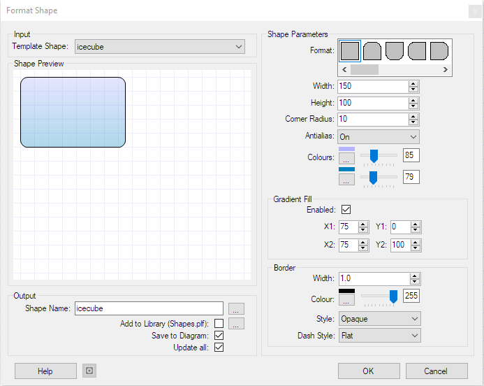
| Template Shape: | Is
a list of shapes populated from the current diagram or library. The selected
shape is used as the starting point for further customization. |
|
| Shape Parameters: | Are the settings which control how the shape is
drawn. |
|
| Format: | Choose from a list of basic shapes. |
|
| Width and Height: | Sets the default width and height of the shape. The
graphic can be resized later using the X/Y scale in the object properties
form. |
|
| Corner Radius:/Offset: | Set corner radius for rectangular shapes.
For parallelogram shapes Offset adjusts the offset of two of the sides. |
|
| Antialias: | Select between On,Off and On rotate. |
|
| Colours: | Choose the background colour of the shape. Select a second
colour if gradient fill is to be used. The slider sets the transparency. |
|
| Gradient Fill: | Tick the enable box to enable gradient fill.
X1,Y1,X2,Y2 sets the start and end coordinates of the gradient fill. |
|
| Border: | Set the width >0 for a border to be displayed. The rest of
the parameters here set the colour and dash style for the border. |
|
| Output, Shape Name: | The name of the customized shape to save. It is important to try and keep customized shape names unique. For example, if you created a new shape called "circle" and there is already a different shape in your diagram called "circle" you will not get the desired result when the new shape is added to your diagram (You cannot over-write an existing shape with another shape by giving it the same name but you can modify the existing shape). The ellipsis button may be used to generate a new random shape name. |
|
| Update all: | Selects whether or not to replace
all shapes in the diagram of the type originally clicked with the new shape
if the name of the shape has changed. |
|
| Save to Diagram: | If you selected format shape by right clicking a
shape in a diagram, this option chooses whether that shape is replaced with
the new shape. |
|
| Save To Library: | When defining a new shape you should tick this box to save the new shape to an Object Library. The elipsis button is used to select a different library to save to. |
Example Shapes |
||
 |
Rectangle, Width=200, Height=100,
background set to transparent by setting the colour slider control to
the left. Arc size 20 sets radiused corners. |
|
|
|
Rectangle, Width=200, Height=100. This variant has only the top two corners radiused. |
See Grouping and Locking for information on combining these shapes in to a composite object.
SCRIPT OBJECTS |
"Script Objects" provide a way to construct vector-based
graphics
for use in Network Notepad from plain-text scripts. Some examples
are available in the
scripts library.
Script Syntax
A Script Object consists of the following statements and commands:
1. The Script Statement.
2. Path Statements.
3. Pens and Brushes.
4. Commands.
5. Align Statements.
Format Script Object
Format Script Object provides an environment for creating and modifying Script Objects. Access it from the Format menu or right-click a Script Object in a diagram or the library window.

To paste a script in to the editor, switch to script view
(Script button) and paste in to the main panel.
Colour
Pickers for pens and brushes are available in the Tabular view
by clicking the elipsis column (...) in the
respective tables.
&hBbGgRr& specifies the Blue, Green and Red
components of the colour in Hex.
Tspcy is the colour
transparency value from 0 to 255, where 255 is solid colour.
The form is resizable and the panels can also be resized by dragging
the horizontal and vertical bars which divide the panels.
Click the Refresh button to apply changes made in the script panels.
Merging Script Objects
Format > Merge Script Objects enables
mulitple Script Objects to be merged in to a single Script Object. Text can
also be merged.
In the following example an small ethernet hub is built up
from components in the online Script Objects Library and then merged:
1. Add the parent object which will act as a container for the
other components.
I have used Format Script Object to create a
box and given the script a new unique name (this is important).
|
|
script "Netgear FE104" 158 25 0.5 brush blue_brush &h8B4001& 255 path name Box path addrectangle 0 0 158 25 fill "Box" blue_brush |
2. Copy and paste script components from the
online library on to the parent object.
I have added four RJ45
sockets and then using the Text tool added a brand label.
![]()
3. Put the parent box and child components in to a
group.
Select the parent Box first followed by the 4 sockets and
the label, then select Format > Group on the ring menu.
The
objects are now loosely bound together.
![]()
4. Select the group by clicking the parent box
and then select Format > Merge Script Objects.
The parent box and
the 5 child objects are now merged into a single Script Object.
|
|
script "Netgear FE104 Hub" 158 25
0.6 brush blue_brush &h8B4001& 255 brush black_brush &h000000& 255 brush silver_brush &hd0d8dc& 255 brush brush1 &hFFFFFF& 255 path name Box path addrectangle 0 0 158 25 path name rj45down path addlines 2 7 2 9 3.5 9 3.5 10 9 10 9 9 10.5 9 10.5 7 12.5 7 12.5 0 0 0 0 7 path name single_port path addrectangle 0 0 15 12 path name path1 path addstring 0 0 NETGEAR arial 3 1 fill "Box" blue_brush fill single_port silver_brush 111.5 8 fill rj45down black_brush 112.5 19 1 -1 fill single_port silver_brush 66.5 8 fill rj45down black_brush 67.5 19 1 -1 fill single_port silver_brush 81.5 8 fill rj45down black_brush 82.5 19 1 -1 fill single_port silver_brush 96.5 8 fill rj45down black_brush 97.5 19 1 -1 fill path1 brush1 5.25 2.25 |
5. To save the new object to the current local library,
right-click the object and select Format Script Object. Click the
"Save to Library" checkbox and click
OK.
Please email me a copy of your new scripts (or any new components) for
inclusion in the online library!
There are a number of restrictions with the Merge Script Objects feature:
The component objects must not be rotated.
The component objects must use their default x-scale and y-scale settings (That will be 1,2 or 4 depending on the Format > Resolution setting).
Name and Address labels are excluded from a merge.
THE SETUP FORM |
The Setup Form
To access the Setup Form select File > Setup from the main ring menu.
 |
General Settings Tab
Language: Select the Language used for Network Notepad.
![]() :
This button opens the selected language translation file for editing.
:
This button opens the selected language translation file for editing.
![]() :
This button refreshes translations from the language translation file.
:
This button refreshes translations from the language translation file.
Show index: To assist with language translations this
temporarily prepends entries with section number and line number to show where
each text entry is located in the language translation file.
Grid Line Spacing: Sets
the spacing for grid lines when grid lines option is switched on
("Options","Grid Lines").
Default IP Address:A partial or complete IP Address which will be applied to all new objects added to the diagram.
Maximum Open Documents: Sets how many documents can be opened at once. Each open document presents its own tab bar at the bottom of the screen.
Reload Document Button:Enables a Reload Document button on the toolbar. This is useful if you edit the diagram outside of Network Notepad and
need to quickly reload the current file.
Default Diagram: Sets the diagram loaded by default if no diagram is specified on the command line. Use the ellipses button to browse for a file or the
"Use Current" button to make the current diagram the default diagram. The "None"
button clears the default diagram.
User-Defined Apps Tab
For information on the User-Defined Apps, see User Defined Apps.
Monitoring Tab
Default Node Settings: Sets the default node settings applied when adding new objects. Node settings are used by add-ons such as NNMonitor to set what actions to take when a node changes state.
Node settings can be changed for individual objects from the "Node" menu when you right-click an object.
Overlays: Sets the style and colour used for overlays set by add-ons such as
NNMonitor and NNPing to indicate the up, down or transitioning state of nodes.
Updates Tab
Enable Automatic Updates: Tick to enable automatic updates (default).
Update Type: Select from Automatic, Check and Download, and Check only.
Manual Proxy Settings: Tick to enable automatic updates with manual proxy server settings.
THE DIAGRAM PROPERTIES FORM |
The Diagram Properties Form
The Diagram Properties Form is accessed from the main ring menu File > Edit Diagram Properties.
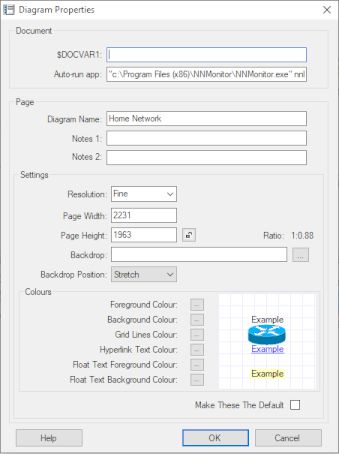
| Document | These first two settings apply to the
whole document. |
| $DOCVAR1: | This is a per-document user variable which can be
passed to user-defined apps. |
| Auto-run app: | A customer requested an option to auto-start
NNMonitor when a document is loaded and this setting is where
this is configured. It can be used to launch any user-defined
app, but with the restriction that it will only run if it
exactly matches the command line of a user-defined app. If it is
not an exact match an error message is displayed. |
| Page | The following settings apply to the
current page. |
| Diagram Name, Notes1, Notes2: | These are text fields stored in the diagram. |
| Settings | |
| Resolution: | Select from Draft, Fine and Superfine. Fine uses a bitmap which is twice as big as Draft and Superfine uses a bitmap which is twice as big as Fine. |
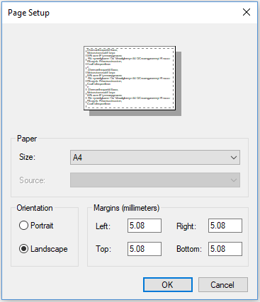
| Page Width and Height: | Specify the size of the page in pixels. See
also Printing. |
| Lock button: | Locks the page width and height so that the
page cannot be resized with the mouse. |
| Backdrop: | Specify an image file for the Backdrop of the diagram. |
| Colours | |
| Forground Colour: and Background Colour: |
Sets the colours used for Object Name and IP Labels. |
| Link Text Colour: | Selects the colour for text used to highlight
objects which link to another diagram. |
| Float Text Foreground and Float Text Background Colours: |
Sets the colours used for Float Text. |
| Make These The Default: | Use the settings specified for this page as the default settings for new diagrams. |
TEMPLATES |
Diagram Templates
When you start a new drawing or add a new page to an existing document,
you are prompted to select from a list of templates. A diagram template is
simply a minimal diagram containing defaults you commonly use in new
diagrams. It
sets the page width, height and orientation and can set text styles, link
styles and some default drawing, for example a title block, border and logo.
Creating Diagram Templates
To create new diagram template, set up a new single page document with
the desired settings and default drawing as mentioned above and then save it
to the templates folder using File > Save to Templates.
MISCELLANEOUS |
Adding A Backdrop Image
Drag and drop a bitmap file (.bmp, .png, .gif or .jpg) on to the page
to use as a backdrop image for your diagram.
In the Diagram Properties form, you may also specify a filename for a
backdrop bitmap, and you can select whether to stretch, centre or tile
the image.
Export To Bitmap Graphics File
To export a diagram as a bitmap file, from the ring menu, select File and then Export To Bitmap Graphics File. Enter a suitable filename when prompted. The following bitmap file types can be selected from drop-down list: .bmp, .gif and .png.
Export To A PDF File
To export a Network Notepad diagram or document to a
searchable PDF file:
File > Export To PDF > Export
Page or Export Document
Setting A Default Diagram
You may configure a default diagram to be displayed when Network Notepad is run. The default diagram is configured in the Setup Form.
Working with CSV files
Network Notepad can save to and load from .csv files which means you
can use a spreadsheet to view and edit diagram files.
In the File
> SaveAs and File > Open dialogs select .CSV file in the type
dropdown list.
Import CSV Data
This feature lets you import a list of Objects from CSV data. Open the form from the menu option File > Import CSV Data.
Note: For cultures which use "," as a decimal separator character use ";" as the delimiter.

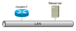
Paste a list of objects in the form in the following format:
Name, Address, Object Type
Example:
router1,10.1.10.1/24,routerc1
switch1,10.1.10.254/24,workgroup switch
PC1,10.1.10.2/24,pc.wmf
When you click the OK button, Network Notepad switches to paste mode and shows the outlines of the objects to be pasted

Paste the objects to complete the operation.

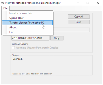
Transfer License To Another PC
When a licensed PC is to be replaced, the Network Notepad license can be transferred to the replacement PC using the procedure shown below. There are a couple of points to be aware of when doing this:
-
Use this procedure only when a complete PC is being replaced. If you are
not replacing a complete PC, such as when upgrading a CPU chip,
replacing a motherboard or replacing a PC but keeping the old hard disk
drive, do not use this procedure. Contact
Support
instead.
-
It is a one-way procedure. You cannot transfer a
license back to the original PC. It is possible to reactivate the
license on the original PC but only with assistance from
Support.
-
As soon as you proceed with the transfer, Network
Notepad will no longer be licensed and will not function the next time
you try to open it.
-
Web browser access to the Internet is required to
create the replacement license file.
|
1. On the PC which is to
be replaced, |
 |
|
2. Click OK at the first confirmation dialog. |
 |
|
3. Tick the "I agree" box and click OK at the second confirmation dialog. |
 |
|
4. Copy the URL displayed to a PC with Internet access and browse to the URL (If you happen to close the dialog at this point, the URL will be displayed again next time you open the License Manager). |
 |
|
5. Fill out the online form and enter the Hardware-ID from the new PC (Run the License Manager on the new PC to display its Hardware-ID) and click Next. |
 |
|
6. Confirm the details on the next page. |
 |
|
7. Download the new PC's license file. A copy is also sent to the email address entered in to the form previously. |
 |
|
8. Copy the license file to the new PC and double-click the file to install it or use the Network Notepad License Manager menu option File > Install a License File. |